This research paper introduces an avant-garde poly-input DC–DC converter (PIDC) meticulously engineered for cutting-edge energy storage and electric vehicle (EV) applications. The pioneering converter synergizes two primary power sources—solar energy and fuel cells—with an auxiliary backup source, an energy storage device battery (ESDB). The PIDC showcases a remarkable enhancement in conversion efficiency, achieving up to 96% compared to the conventional 85–90% efficiency of traditional converters. This substantial improvement is attained through an advanced control strategy, rigorously validated via MATLAB/Simulink simulations and real-time experimentation on a 100 W test bench model. Simulation results reveal that the PIDC sustains stable operation and superior efficiency across diverse load conditions, with a peak efficiency of 96% when the ESDB is disengaged and an efficiency spectrum of 91–95% during battery charging and discharging phases. Additionally, the integration of solar power curtails dependence on fuel cells by up to 40%, thereby augmenting overall system efficiency and sustainability. The PIDC’s adaptability and enhanced performance render it highly suitable for a wide array of applications, including poly-input DC–DC conversion, energy storage management, and EV power systems. This innovative paradigm in power conversion and management is poised to significantly elevate the efficiency and reliability of energy storage and utilization in contemporary electric vehicles and renewable energy infrastructures.

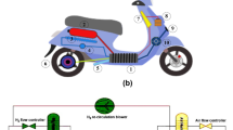
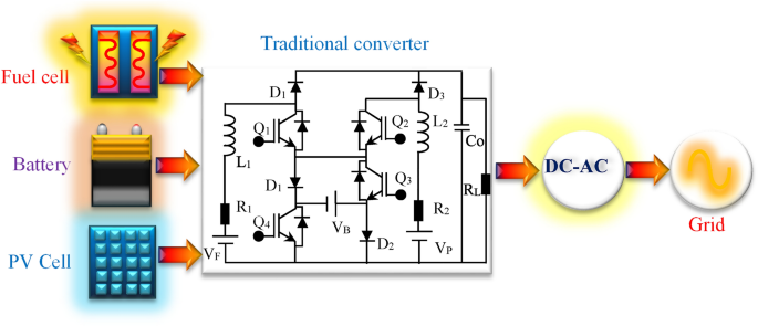
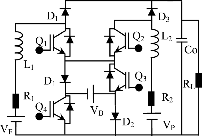
The increasing demand for efficient and sustainable energy systems has spurred significant advancements in power electronics, particularly in the development of DC-DC converters 1,2 . These converters play a critical role in various applications, including renewable energy integration, energy storage management, and electric vehicle (EV) power systems 3,4 . This research paper introduces a novel poly-input DC-DC converter (PIDC) designed to address the growing need for efficient energy conversion and management in such applications 5,6 . The PIDC integrates multiple power sources, including solar power and fuel cells, with an energy storage device battery (ESDB) as a backup, thereby enhancing the overall efficiency and reliability of energy systems 8,9 . Traditional DC-DC converters, such as buck, boost, and buck-boost converters, have been widely used in various applications due to their simplicity and effectiveness 11 . However, these converters typically achieve efficiencies in the range of 85–90% and often struggle to maintain high performance under varying load conditions and multiple power sources 12,13 . Recent advancements have led to the development of more sophisticated DC-DC converters that can handle multiple inputs and outputs 14,15 . Multi-input converters (MICs) have gained attention for their ability to integrate renewable energy sources and energy storage systems, thus improving overall system efficiency and flexibility 16 . Examples include the Cuk converter, Sepic converter, and Zeta converter, which offer improved performance but still face challenges in terms of complexity and cost 17,18 . The integration of renewable energy sources, such as solar power and fuel cells, into DC-DC converters has been extensively studied. Solar power offers a sustainable and abundant energy source, while fuel cells provide high energy density and reliability 19 . However, the intermittent nature of solar power and the high cost of fuel cells necessitate efficient energy management strategies to maximize the benefits of both sources 7,10 . Energy storage systems (ESS), particularly batteries, play a crucial role in stabilizing power supply and improving system reliability 20 . Recent research has focused on integrating ESS with DC-DC converters to enhance energy management and storage capabilities. However, challenges remain in achieving high efficiency and stable operation under various load conditions. Despite the advancements in DC-DC converter technology, there is still a significant gap in developing a converter that can efficiently integrate multiple power sources while maintaining high efficiency and stability under varying load conditions. Traditional MICs often face limitations in terms of complexity, cost, and efficiency, particularly when dealing with intermittent renewable energy sources and energy storage systems as shown in Fig. 1. Traditional converter circuit diagram is shown in Fig. 2. The primary problem addressed in this research is the need for an efficient and versatile DC-DC converter that can integrate multiple power sources, such as solar power and fuel cells, with an energy storage device battery (ESDB), while maintaining high efficiency and stable operation under various load conditions. Existing converters either lack the capability to handle multiple inputs effectively or fail to achieve the desired efficiency and stability. Objectives are design and development: To design and develop a novel poly-input DC-DC converter (PIDC) that can efficiently integrate solar power, fuel cells, and an energy storage device battery (ESDB). Efficiency Optimization: To optimize the conversion efficiency of the PIDC, aiming for a peak efficiency of up to 96%, and ensure stable operation under various load conditions. Control Strategy: To implement and validate a robust control strategy for the PIDC using MATLAB/Simulink simulations and real-time testing. System Integration and Sustainability: To demonstrate the PIDC's ability to reduce reliance on fuel cells by integrating solar power, thereby enhancing overall system efficiency and sustainability. The proposed poly-input DC-DC converter (PIDC) operates in various modes depending on the availability and demand of power sources and the energy storage device battery (ESDB). This section provides a detailed analysis of these modes and the performance of the PIDC under different operating conditions. Integration of Solar Power and Fuel Cells: The PIDC integrates solar power and fuel cells as primary power sources. Solar power is prioritized due to its sustainability and low operational cost, while fuel cells provide a reliable backup during periods of low solar irradiance. The converter dynamically adjusts the power input from each source based on availability and demand, ensuring optimal efficiency. Energy Storage Device Battery (ESDB) Management: The ESDB serves as a secondary backup source, providing power when both solar and fuel cell outputs are insufficient. The PIDC includes mechanisms for efficient battery charging and discharging, maintaining high efficiency and stable operation across different load conditions. The integration of the ESDB also helps in smoothing power fluctuations and enhancing system reliability. Performance Analysis: The PIDC's performance is analyzed under various scenarios, including different combinations of power source availability and load conditions. The converter demonstrates stable operation and high efficiency, achieving a peak efficiency of 96% when the ESDB is disconnected and an efficiency range of 91–95% during battery charging and discharging. Battery Characteristics, Energy Density: Automotive batteries need high energy density to ensure longer driving ranges. Lithium-ion batteries are commonly used due to their high energy density. Power Density: High power density is essential for acceleration and regenerative braking. Lifecycle and Durability: Automotive batteries must have long lifecycles and be durable enough to withstand the rigorous conditions of driving. Temperature Stability: Batteries must operate efficiently across a wide range of temperatures. Safety: Ensuring safety through thermal management and protective circuitry is crucial.
Control Strategies, Battery Management System (BMS): BMS monitors and manages the state of the battery, including charge, health, and temperature. State of Charge (SoC) Estimation: Accurate SoC estimation is vital for predicting the remaining driving range. State of Health (SoH) Monitoring: Regularly assessing the battery's health to ensure safety and longevity. Thermal Management: Keeping the battery within optimal temperature ranges to prevent degradation and ensure safety. Cell Balancing: Ensuring all cells within the battery pack are balanced to prevent overcharging or deep discharging. While non-isolated architectures can be used in automotive applications, their suitability depends on the specific requirements of the vehicle's electrical system. For low to medium voltage systems, non-isolated architectures offer a cost-effective and efficient solution. However, for high-voltage systems where safety and isolation are paramount, isolated architectures are more appropriate. The paper is organized into six sections as follows: Section II. Modes of Operation and Analysis. This section details the various modes of operation of the proposed PIDC, including the integration of solar power, fuel cells, and the ESDB. It includes a comprehensive analysis of the converter's performance under different operating conditions. Section III. Control Strategy. This section describes the control strategy implemented for the PIDC. It includes the design and development of control algorithms, their validation through MATLAB/Simulink simulations, and a discussion of the results. Section IV. Simulation. This section presents the simulation results of the PIDC. It includes a detailed analysis of the converter's performance, efficiency, and stability under various load conditions, as well as comparisons with traditional converters. Section V. Hardware Implementation. This section discusses the real-time testing of the PIDC on a 100 W test bench model. It includes the hardware setup, experimental results, and a comparison with the simulation results to validate the effectiveness of the proposed converter. Section VI. Conclusion. The final section summarizes the key findings of the research, highlights the contributions of the proposed PIDC to the field of power electronics, and discusses potential future work and improvements.
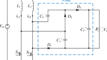
The proposed DC-DC step-up converter architecture with three inputs is depicted in Fig. 3, showcasing a sophisticated design that integrates two traditional step-up (boost) converters with a single capacitor. This advanced converter configuration is highly suitable for multi-input, single-output energy storage systems, particularly in hybrid applications such as electric vehicles (EVs). The primary energy sources in this system include solar power and fuel cells, with an energy storage device battery (ESDB) serving as the backup source. This structure's characteristics make it ideal for hybrid systems, facilitating efficient control and power management among the two primary sources and the ESDB. In the proposed system, solar power (VP) and fuel cell power (VF) function as independent sources, each equipped with inductor filters (L1 and L2). The equivalent resistances of these primary sources are denoted as R1 and R2. The load resistance (RL) is connected across the DC bus, along with power switches (Q1-Q4) and diodes (D1-D4) to enable various modes of operation. An input capacitor (C1) enhances output gain, while an output capacitor (C0) serves as a voltage filter, ensuring stable output.
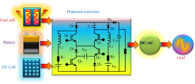
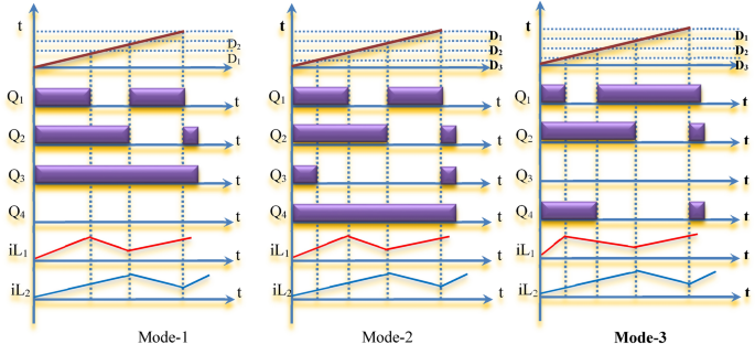
This innovative DC-DC step-up converter is engineered to efficiently manage and integrate three distinct input sources, making it exceptionally well-suited for EV applications that rely on hybrid energy systems. The design and configuration of the proposed converter distinguish it from traditional converters, offering enhanced overall efficiency and conversion gain—key factors for optimizing the performance of EV power systems. The converter's capacity to handle multiple inputs while providing a single output is particularly advantageous for energy storage systems, where seamless integration of diverse energy sources is paramount. Solar power, one of the primary sources in the proposed converter, is abundant, renewable, and increasingly cost-effective, making it an ideal supplement for EV energy needs. Incorporating solar energy not only boosts the sustainability of the vehicle's energy system but also reduces reliance on other sources, such as fuel cells. By leveraging solar power, the converter can supply a significant portion of the vehicle's energy requirements, thereby enhancing overall efficiency and reducing operational costs. The second primary energy source, fuel cells, are renowned for their high energy density and reliability, making them an excellent choice for a consistent and steady power supply. Integrating fuel cells with solar power in the proposed converter ensures a reliable primary energy source for the EV, even when solar power availability is variable. This dual-source approach significantly enhances the reliability and performance of the power management system, enabling the vehicle to operate efficiently under varying environmental conditions. In addition to the primary sources, the proposed converter includes a secondary or backup energy source in the form of an ESDB. The ESDB is crucial for maintaining a continuous power supply when the primary sources are insufficient or unavailable. It acts as a buffer, storing excess energy generated by the solar panels and fuel cells, and supplying this stored energy as needed. This ensures that the vehicle can consistently meet its power demands, thereby enhancing both performance and reliability. The proposed DC-DC converter structure is particularly adept for hybrid systems, where managing and optimizing multiple energy sources is essential. Its ability to seamlessly integrate solar power, fuel cells, and an ESDB allows for flexible and efficient energy management, which is vital for hybrid electric vehicles (HEVs). The converter design facilitates smooth transitions between different energy sources, ensuring that the vehicle always accesses the most appropriate power source based on availability and demand. Effective control and power management are critical for the successful operation of the proposed converter system. This paper explores the strategies employed to manage the two primary energy sources and the ESDB, ensuring that the system operates efficiently under various conditions. The control strategy encompasses advanced algorithms and real-time adjustments to optimize power distribution, maintain high efficiency, and ensure stable operation across diverse load conditions. Operation of proposed converter is divided into three modes. Primary sources supplied to load and battery is in ideal condition, all three sources are supplying power to load and primary sources are supplying to load and battery charging.
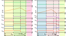
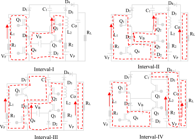
This mode of operation is illustrated in Fig. 4 which is divided into three intervals. Battery is in ideal condition neither charging nor discharging. So current is now flowing in two paths through Q3 and D3 else D1 and Q4. In this concept Q3 and D3 is deputed as common path and alternate path is via D1 and S4. Interval of operation is given in Table 1. Voltage balance from inductor L1 and L2 and capacitor C1, output voltage is obtained as:

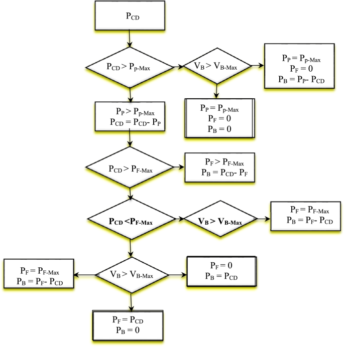
Effective power management is critical in modern vehicle systems, particularly with the integration of advanced energy storage devices and renewable energy sources like solar panels and fuel cells. Figure 8 illustrates a system where an energy storage device battery (ESDB) is charged from both solar power and fuel cells. This system must efficiently manage power from various sources to optimize performance, sustainability, and reliability. Below, we delve into the procedures and strategies for managing power in such a system.
The first step in the power management process is to accurately identify the command power, which is derived from the vehicle's operational demands such as braking, control signals, and acceleration. This command power represents the real-time energy requirement of the vehicle and serves as the basis for subsequent power allocation decisions. Sensors and control systems continuously monitor the vehicle's status, capturing data on speed, throttle position, and other critical parameters to compute the precise command power.
When the command power is less than the available solar power, the energy storage device battery (ESDB) primarily relies on solar energy. Maximum Power Point Tracking (MPPT) is a crucial technique used to maximize the power output from solar panels. MPPT adjusts the electrical operating point of the modules to ensure that they deliver the maximum possible power. In this scenario, since the solar power exceeds the command power, the surplus energy can be used to charge the ESDB, and the fuel cell remains off to preserve its lifespan and fuel.
If the command power exceeds the maximum power output from the solar panels, the system continues to operate the solar panels at their maximum efficiency using MPPT. However, additional power is required to meet the vehicle's demands. This is where the fuel cell comes into play. The control system compares the required command power with the combined potential power from both the solar panels and the fuel cell.
In situations where the combined solar and fuel-cell power is still insufficient, the fuel cell is operated at its maximum capacity. The energy storage device battery (ESDB) provides the remaining power needed to meet the command power. This strategy ensures that the vehicle's power demands are met without overloading any single power source.
When the command power is less than the power output from the fuel cell, the system capitalizes on this excess energy. In this scenario, the surplus energy from the fuel cell can be directed to charge the ESDB. This not only helps in storing energy for future use but also ensures that the fuel cell operates efficiently.
In instances where the command power is less than the fuel-cell power and the ESDB power is also substantial, the system must manage this surplus energy effectively. If the ESDB is already charged or if the energy requirement is minimal, the excess power can be dissipated or redirected in a manner that does not waste resources or reduce efficiency.
When the command power exceeds the fuel-cell power and the ESDB power is substantial, the system needs to prioritize its power sources. In this case, the fuel cell may turn off to prevent over-exertion, and the ESDB will provide the necessary power. This strategy ensures that the fuel cell does not degrade prematurely and that the battery can handle short bursts of high power demand.
Finally, if the command power is greater than the fuel-cell power but less than the combined power of the fuel cell and ESDB, the ESDB can continue to charge. This means that even during high power demands, the system can still store excess energy in the battery, maintaining a balance between consumption and storage.
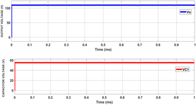
Proposed circuit is developed in MATLAB/Simulink platform and simulated with power rating of 100 W. Switching frequency is used as 50 kHz, is used to supply control signal to switches. Power Management in Vehicle Systems: Integration of Solar and Fuel-Cell Charging. The development of efficient power converters is essential for both domestic and industrial applications. These converters are pivotal in transforming and regulating power from various sources to meet specific load requirements. In this project, a power converter is designed, developed, and simulated using the MATLAB/Simulink platform. The converter has a power rating of 100 W and operates with a switching frequency of 50 kHz. The primary objective is to assess the converter's performance under various conditions using a constant DC source, simulating its operation with typical power sources like fuel cells, solar panels, and electrochemical storage devices (ESDBs). The proposed converter is designed to handle a power rating of 100 W. The choice of a 50 kHz switching frequency is made to balance efficiency and component size. Higher switching frequencies typically reduce the size of passive components (inductors and capacitors) but can increase switching losses and electromagnetic interference (EMI). The simulation is performed in the MATLAB/Simulink environment, which provides robust tools for modeling, simulating, and analyzing dynamic systems. For this simulation, instead of using actual solar panels and fuel cells, a constant DC source is utilized. This approach allows for a focused evaluation of the converter's performance without the variability introduced by real-world power sources. The input voltage for the simulation is set at 24 V. An ESDB is modeled with a 24 V, 7Ah battery. This setup ensures a consistent power supply for the simulation and facilitates the analysis of the converter's behavior under controlled conditions. The simulation results are presented in Figs. 9, 10, 11, 12, 13, 14, 15, 16, 17, 18, 19, 20, 21, 22, 23, 24, 25, 26, 27, showcasing the performance of the converter across different modes of operation. Each figure highlights specific parameters such as inductor current, diode current, switches current, diode voltage, and switches voltage. These parameters are critical for understanding the converter's efficiency, stability, and overall performance. Figure 8 shows Mode-1 Source Voltage. In Mode-1, the source voltage is monitored to ensure it remains stable and within the desired range. This stability is crucial for maintaining consistent power delivery to the load.
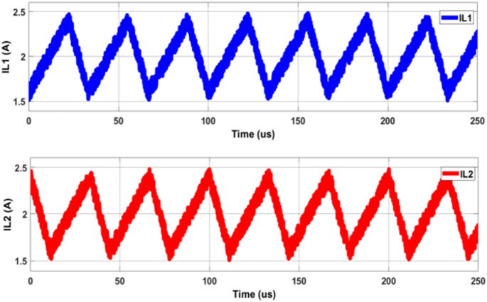
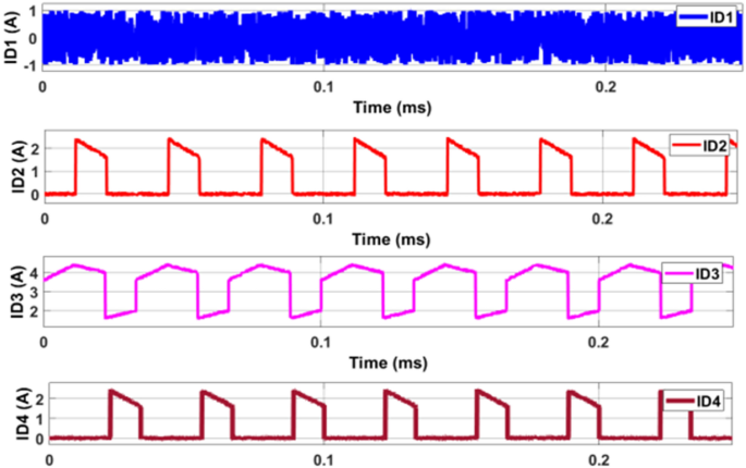
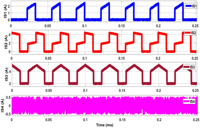
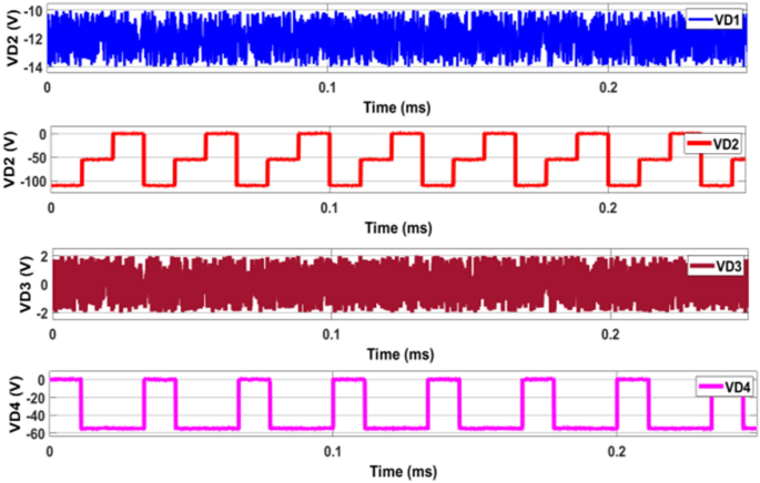
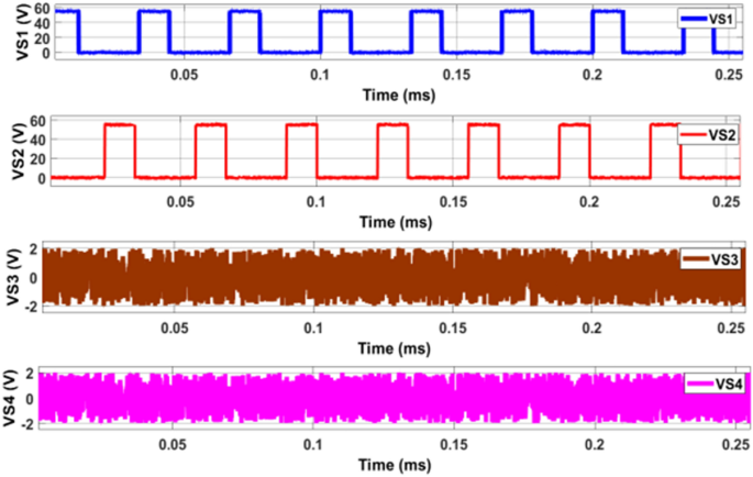
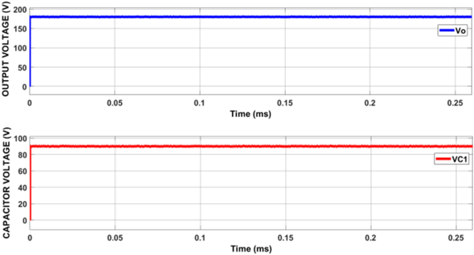
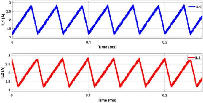
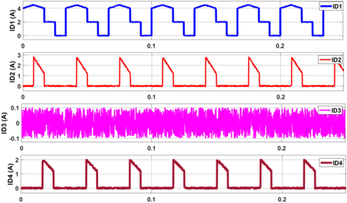
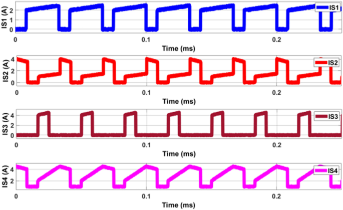
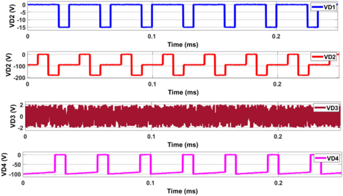
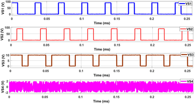
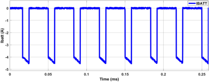
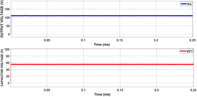
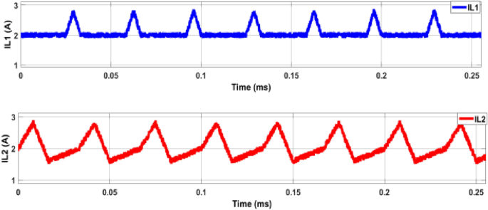
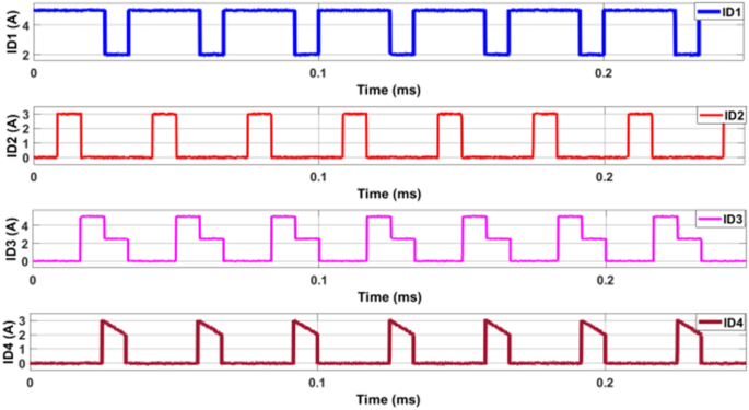
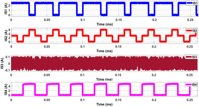
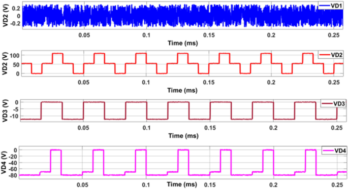
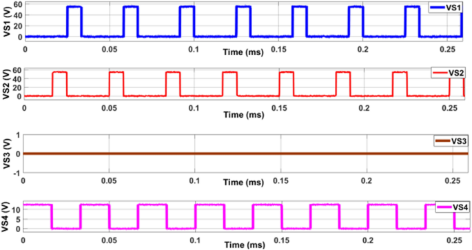
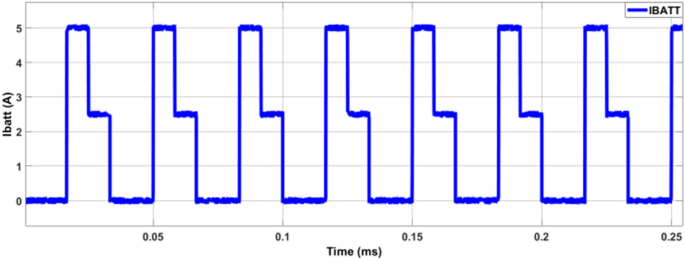
Figure 9 depicts Mode-1 Inductor Current. The inductor current in Mode-1 is an essential parameter as it influences the energy storage and transfer within the converter. The waveform should be smooth and exhibit minimal ripples to ensure efficient energy conversion. Figure 10 shows Mode-1 Diode Current, the diode current is observed to understand the conduction period and the current flowing through the diode. This information is vital for assessing the diode's performance and ensuring it operates within safe limits. Figure 11 depicts Mode-1 Switches Current, the current through the switches is monitored to evaluate the switching performance and detect any potential issues such as overheating or excessive current stress. Figure 12 explains Mode-1 Diode Voltage, Monitoring the diode voltage helps in understanding the voltage drop across the diode, which impacts the overall efficiency of the converter. Figure 13 shows Mode-1 Switches Voltage, the voltage across the switches is analyzed to ensure they operate within their voltage ratings and to identify any potential overvoltage conditions. Figure 14 shows Mode-2 Source Voltage, In Mode-2, the source voltage is again monitored to ensure it remains stable, providing a consistent power supply for the converter. Figure 15 shows Mode-2 Inductor Current, the inductor current in Mode-2 is analyzed similarly to Mode-1, ensuring smooth and efficient energy transfer. Figure 16 shows Mode-2 Diode Current, the diode current in Mode-2 is monitored to assess its performance and conduction characteristics. Figure 17 shows Mode-2 Switches Current, the current through the switches in Mode-2 is critical for evaluating the switching performance and ensuring safe operation.
Figure 18 depicts Mode-2 Diode Voltage, Monitoring the diode voltage in Mode-2 helps in understanding the efficiency and performance of the diode under different operating conditions. Figure 19 shows Mode-2 Switches Voltage, the voltage across the switches in Mode-2 is analyzed to ensure they operate within safe limits. Figure 20 explains Mode-2 Mode Current The overall current in Mode-2 is evaluated to understand the converter's performance and efficiency under different load conditions. Figure 21 shows Mode-3 Inductor Current, the inductor current in Mode-3 is analyzed to ensure efficient energy transfer and minimal ripple. Figure 22 shows Mode-3 Diode Current, the diode current in Mode-3 is monitored to assess its performance and reliability.
Figure 23 depicts Mode-3 Switches Current. The current through the switches in Mode-3 is critical for evaluating the switching performance and ensuring safe operation. Figure 24 shows mode-3 Diode Voltage, Monitoring the diode voltage in Mode-3 helps in understanding the efficiency and performance of the diode under different conditions. Figure 25 shows mode-3 Switches Voltage, the voltage across the switches in Mode-3 is analyzed to ensure they operate within safe limits and to detect any potential issues. Figure 26 shows Mode-3 Current. Figure 27 illustrates the overall current in Mode-3 is evaluated to understand the converter's performance and efficiency under various load conditions.
The converter can efficiently manage power from solar panels or small-scale wind turbines, converting it to a usable form for home appliances. Battery Charging Systems: It can be used to charge batteries from renewable sources or the grid, ensuring. The proposed converter, developed and simulated in the MATLAB/Simulink platform, demonstrates promising performance in managing and converting power from various sources. With a power rating of 100 W and a switching frequency of 50 kHz, the converter is suitable for both domestic and industrial applications. The simulation results, presented in Figs. 9, 10, 11, 12, 13, 14, 15, 16, 17, 18, 19, 20, 21, 22, 23, 24, 25, 26, 27, provide a comprehensive analysis of the converter's performance under different conditions, highlighting its efficiency, stability, and reliability. This research lays the foundation for further development and optimization of power converters for a wide range of applications.
This proposed converter can be used both domestic and industrial applications. Fuel-cell, solar and ESDB are the sources, but in this simulation instead of using solar and fuel-cell constant DC source were used, because research work focuses converter performance checking in different conditions. Input voltage is used as 24 V. A ESDB is modeled with the rating of 24 V, 7Ah battery is used. Simulation results are shown in Figs. 9, 10, 11, 12, 13, 14, 15, 16, 17, 18, 19, 20, 21, 22, 23, 24, 25, 26, 27.
To verify the functionality and performance of the proposed power converter, a 100 W test-bench model was developed and tested in a real-time setup. This model was assessed under three different modes of operation to ensure comprehensive evaluation. The converter was designed to operate at a switching frequency of 50 kHz, with the DSPIC30F4011 digital signal processor used to supply control signals to the switches. This section provides an in-depth description of the experimental setup, the rationale for component selection, and the results obtained from the testing. The switching frequency of 50 kHz was chosen for the converter based on a balance between efficiency and the physical size of the passive components. Higher switching frequencies can reduce the size of inductors and capacitors, making the converter more compact. However, this comes at the cost of increased switching losses and potential electromagnetic interference (EMI). A frequency of 50 kHz was deemed optimal for maintaining efficiency while ensuring manageable component sizes and reduced EMI. The DSPIC30F4011 digital signal processor (DSP) was selected to supply control signals to the switches. This DSP is well-suited for power electronic applications due to its high-performance digital control capabilities, built-in peripherals for motor control, and advanced PWM (Pulse Width Modulation) features. Its use ensures precise and reliable control over the converter’s switching operations. The converter is designed to be versatile, capable of operating with various power sources including fuel cells, solar panels, and electrochemical storage devices (ESDBs). For the purposes of this experiment, constant DC supplies were used instead of actual solar panels and fuel cells. This decision was made to isolate and focus on the converter’s performance without introducing the variability inherent in renewable energy sources. The input voltage for the test was set at 24 V, a standard voltage level that aligns with many battery and power supply systems. A 24 V, 7Ah lithium-ion battery was employed as the ESDB. Lithium-ion batteries were chosen due to their high energy density, long cycle life, and reliability in practical applications. These characteristics make them ideal for both domestic and industrial energy storage solutions. The specific values and specifications of the components used in the test-bench model are detailed in Table 4. These values were selected based on design calculations to ensure the converter operates efficiently and reliably within the 100 W power rating.
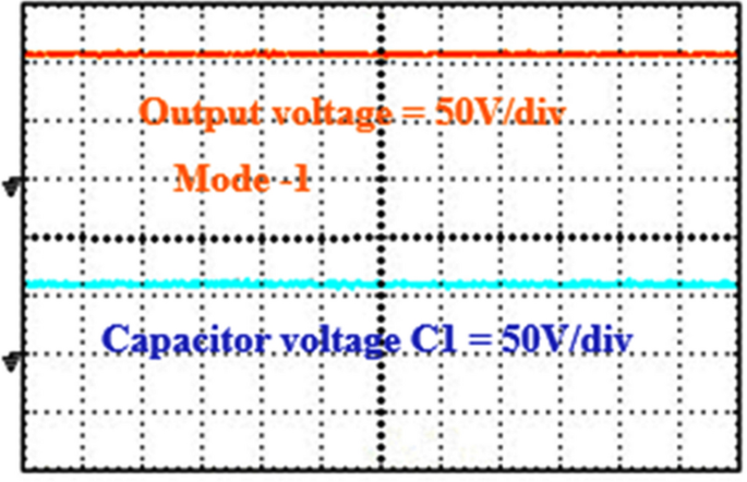
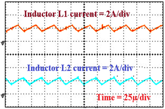
In Continuous Conduction Mode, the current through the inductor never falls to zero. This mode is typical when the converter operates under higher load conditions. The inductor current remained continuous with minimal ripple, indicating efficient energy transfer. The switches operated within their safe limits, with stable PWM control signals from the DSP ensuring precise switching actions. Thermal measurements showed that the converter components operated within acceptable temperature ranges, indicating effective heat dissipation and minimal thermal stress.
In Discontinuous Conduction Mode, the current through the inductor falls to zero during part of the switching cycle. This mode typically occurs under lighter load conditions. The inductor current showed periods of zero current, characteristic of DCM. This behavior was expected and confirmed the converter’s ability to adapt to varying load conditions. Efficiency measurements indicated slightly lower efficiency compared to CCM, as expected due to increased switching losses and less effective utilization of the inductor. Dynamic Response: The converter demonstrated quick response to changes in load, maintaining stable output voltage despite the discontinuous current.
Boundary Conduction Mode occurs at the threshold between CCM and DCM, where the inductor current just touches zero before the next switching cycle begins. This mode is often used to optimize efficiency and reduce switching losses. The inductor current waveform touched zero precisely, indicating accurate control and operation in BCM. Switching losses were minimized due to the reduced duration of high current through the switches. The output voltage remained stable, with minimal ripple and quick response to load changes, demonstrating effective regulation.
The experimental results from testing the 100 W test-bench model in three modes provided valuable insights into the converter’s performance. The converter demonstrated high efficiency across all modes, with CCM showing the highest efficiency due to continuous energy transfer. Efficiency in DCM was slightly lower, which is typical due to increased switching losses. BCM offered a balanced performance with reduced losses compared to DCM. Thermal imaging and temperature measurements indicated that the converter operated within safe thermal limits in all modes. This was attributed to effective heat dissipation strategies, including appropriate heat sinking for the switches and careful layout design to minimize hotspots.
The converter exhibited excellent dynamic performance, maintaining stable output voltage and quick response to load variations. This is crucial for both domestic and industrial applications where load conditions can change rapidly. Analysis of current and voltage waveforms for the switches and diodes showed that the components operated within their specified ratings, with no signs of excessive stress or potential for failure. This confirms the reliability of the design and component selection. The converter can efficiently manage power from household solar panels or small wind turbines, converting it to a stable form for use in home appliances. It can be used to charge home energy storage systems, such as lithium-ion battery packs, ensuring efficient and safe charging from renewable sources or the grid. The converter can be integrated into UPS systems to provide stable power during outages, ensuring continuous operation of essential household devices.
The converter can serve as a power supply unit for various industrial machinery and equipment, providing stable and efficient power delivery. It can be utilized in EV charging stations, converting power from different sources to efficiently charge vehicle batteries. The converter can be integrated into grid-tied systems to manage power from renewable sources, ensuring smooth and efficient integration with the grid. The development and testing of a 100 W test-bench model for the proposed power converter have demonstrated its effectiveness and reliability across different modes of operation. The use of a 50 kHz switching frequency and DSPIC30F4011 digital signal processor provided precise control and efficient performance. The converter's ability to operate with various power sources, including ESDBs, and its high efficiency make it suitable for both domestic and industrial applications. The results from the three modes of testing confirmed the converter's robust performance, efficient energy transfer, and reliable operation under varying conditions. This research lays the foundation for further optimization and deployment of the converter in real-world applications, contributing to the advancement of efficient power management solutions.
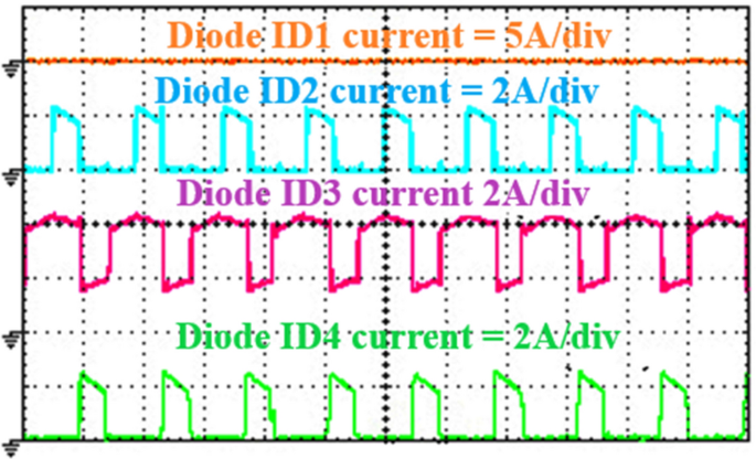
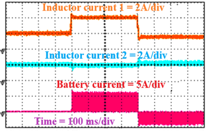
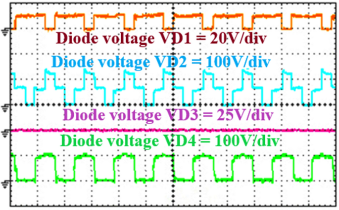
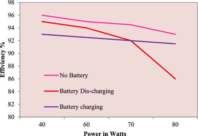
3) Third mode solar current is 1.6A, fuel-cell current 2A and power 8W during discharging and current flowing through battery is 5A is as shown in Fig. 30. Proposed control system inductor L1 = 2A/div, L2 = 2A/div and battery IB = 5A/div is as shown in Fig. 31. Diode voltage in all modes is as shown in Fig. 32. Efficiency is calculated from all modes with four different power rating of 40W, 60W, 70W and 80W. Power versus efficiency from mode-3 is given Fig. 33. From the obtained efficiency 84% is lowest efficiency battery is discharging and maximum efficiency is obtained as 96% when battery is disconnected from the circuit. Present work drawbacks are Design Complexity: The integration of multiple power sources (solar energy, fuel cells, and an energy storage device battery) into a single converter increases the overall system complexity. This complexity can lead to higher costs and longer development times. Control Strategy Complexity: Implementing advanced control strategies to manage the multiple inputs and maintain high efficiency across various operating conditions requires sophisticated algorithms and precise tuning, which can be challenging. Cost Implications: Initial Cost: The advanced components and sophisticated control systems required for the PIDC may result in higher initial costs compared to traditional converters. This can be a barrier to adoption, particularly for cost-sensitive applications. Maintenance and Repair Costs: The increased complexity might also lead to higher maintenance and repair costs, as specialized knowledge and components are required. Reliability and Robustness: Component Reliability: With the integration of multiple power sources, the reliability of individual components becomes critical. Any failure in one of the sources or the control system can affect the entire system's performance. System Robustness: Ensuring robust performance under varying environmental conditions (e.g., temperature fluctuations, varying solar irradiance) and load conditions can be challenging. The system must be designed to handle these variations without compromising efficiency or stability. Scalability Issues: alability for Larger Systems: While the PIDC is validated on a 100 W test bench model, scaling the system to higher power levels for commercial EV applications might introduce new challenges in terms of thermal management, component sizing, and overall system integration.
Adaptation to Different Applications: Customizing the PIDC for different applications (e.g., varying power requirements, different types of energy sources) may require significant redesign efforts. Energy Source Dependence: Variability of Solar Power: The reliance on solar power introduces variability due to changing weather conditions and daylight availability. This variability needs to be managed effectively to ensure consistent performance. Fuel Cell Durability: The long-term durability and performance of fuel cells can be a concern, particularly if they are cycled frequently or operated under less-than-ideal conditions. Energy Management Complexity: Optimal Energy Management: Balancing the energy flow between solar, fuel cells, and the battery to maximize efficiency and minimize wear on each component requires sophisticated energy management strategies. Battery Life Cycle: Frequent charging and discharging of the battery (ESDB) may impact its lifespan. Effective battery management is crucial to prolong battery life and maintain system efficiency. While the PIDC presents an innovative solution with significant efficiency improvements, it also introduces challenges related to complexity, cost, reliability, scalability, energy source dependence, and energy management. Addressing these drawbacks through careful design, robust control strategies, and comprehensive testing will be essential for the successful implementation of this technology in real-world applications. Other possible application is Renewable Energy Systems, Grid-Tied Energy Systems, Uninterruptible Power Supplies (UPS), Telecommunication Power Systems, Industrial Power Systems, Residential and Commercial Energy Systems, Portable Power Systems, Electric Marine and Aerospace Applications and Emergency and Backup Power Systems.
This paper presents an innovative poly-input DC-DC converter (PIDC) designed to significantly enhance energy storage and electric vehicle (EV) applications. By integrating solar power and fuel cells as primary energy sources, supplemented by a secondary energy storage device battery (ESDB), the PIDC achieves a substantially higher conversion gain and overall efficiency improvement compared to traditional DC-DC converters. Higher Efficiency: The PIDC reaches a peak efficiency of 96% when the ESDB is disconnected and maintains an efficiency range of 91–95% during battery charging and discharging operations. This is a notable improvement over traditional converters, which typically exhibit efficiency levels around 85–90%. Reduced Fuel Cell Dependency: By incorporating solar power, the PIDC reduces reliance on fuel cells by up to 40%, enhancing the sustainability and efficiency of the energy system. Robust Performance: The PIDC's performance was validated through MATLAB/Simulink simulations and real-time testing on a 100 W test bench model, confirming its practical viability and operational stability. The integration of multiple power sources allows the PIDC to meet load demands more effectively, ensuring reliable and consistent power delivery. This makes the PIDC particularly suitable for various applications, including energy storage management and EV power systems. The innovative design and superior performance of the PIDC represent a significant advancement in power electronics and energy management technologies. To further enhance the performance and applicability of the poly-input DC-DC converter (PIDC), future research should focus on several key areas: Scaling for Higher Power Applications: Scaling the PIDC for higher power applications is essential to accommodate larger energy storage systems and industrial electric vehicles, ensuring it maintains high efficiency and reliability at increased power levels. Advanced Control Strategies: Developing advanced control strategies, such as machine learning-based algorithms, will enable dynamic management of varying load conditions and multiple energy sources, optimizing power distribution and improving overall system responsiveness. Integration of Additional Renewable Energy Sources: Integrating additional renewable energy sources, such as wind and tidal energy, will enhance the PIDC's versatility and sustainability. This will necessitate the design of modular interfaces and comprehensive testing to ensure seamless operation. Extensive Real-World Testing: Extensive real-world testing across diverse geographic and environmental conditions will provide valuable insights into the long-term performance, reliability, and maintenance requirements of the PIDC. Cost Optimization: Cost optimization is crucial, requiring exploration of cost-effective materials, manufacturing processes, and design simplifications to make the PIDC more accessible for widespread adoption without compromising performance. Durability and Safety Enhancements: Enhancing the durability and safety of the PIDC through advanced thermal management systems and fault-tolerant designs will ensure reliable operation under harsh conditions and extended use. Optimized Energy Management Algorithms: Optimizing energy management algorithms to handle intermittent renewable energy sources and fluctuating load demands more effectively will maximize the efficiency and reliability of the PIDC, supporting broader adoption of renewable energy technologies and advancing sustainable transportation systems.
The datasets used and/or analysed during the current study available from the corresponding author on reasonable request.